It’s time to get back to the workshop and start building again. I still need to finish my Diana4, which has been on the back burner while I finished my Monerai. In addition, we are resuming the work on the Neukom Elfe S3.
In the past few weeks, Georg has prepared the parting plane for the fuselage plug. I helped him set up the workshop to prepare building the fuselage moulds and fitting the plug into the parting plane (so that it’s perfectly centered). He will now fill the gap between the plug and parting plane with paste (the same stuff used by dentists to make moulds for teeth) and wax the plug and parting plane.
We also started cutting the styro foam for the wings and elevators.Over summer Georg built a nifty foam cutting installation. It works really well and ensures an even nicer hot wire cut than the manual cutting we did in the past.
This year’s annual club outing to Hahnenmoos in June was great. We spent many hours flying in excellent weather, especially at my favourite flying spot Luegli. With many flying hours unfortunately also the risks of damage increase – especially landing on alpine slopes. I misjudged the landing of my Chocofly DG800 after a few hours of flying in Luegli and came in too fast on a down-sloping hill. During the landing the plane’s wing caught on a lump of grass, causing the plane to twist in the last few meters of the landing and the tail boom of the DG800 snapped in two. Fortunately it was a clean break and the plane had no significant further damage.
In my collection of cardboard tubes I found one that was approximately the size of the tail boom. I covered this with cling film and then laminated a carbon sleeve around it (covering it with peel ply so that it’s nice and tight and is also easier to laminate into the fuselage). Once the resin was cured I cut the sleeve across so that it perfectly fit the inside of both sides of the tail boom. I then epoxied this sleeve into the plane – taking care that the tail was exactly in the right place. After letting this cure I added a few bits of 50gr glass to close any remaining gaps, together with some resin thickened with micro-balloons and finished it off with a layer of 50gr glass all around the repair. After lots of sanding – primer – sanding I spray painted it with 2 component paint.
On Monday my Monerai had its first flight on our favourite slope in Toggenburg. My mate Richi, who designed and built the first Monerai, as well as built the fuselage mould, took his Monerai as well – the first time we had both of them flying together. We had great lift and my Monerai was up for three hours in a single flight. It’s such a fun little plane to fly on the slope. I was amazed by how fast it picks up speed, even with only 3.7 kg (I easily hit 220kmh on one the quick passes). It allows for very tight turns. I added quite a bit of snap-flap, further increasing its ability to pick up thermals. It also rolls very nicely. Of course it’s nothing like our bigger gliders in terms of course stability and climbing rate in light lift, but that’s obvious from the glider’s design. It’s a lovely small light plane to play with on nice slope days. This one will also join the selection of gliders coming to Hahnenmoos in June.
The plugs for the fuselage and the rudder are ready. Our shaper Richi has done an amazing job, as usual. The part where the wings join the fuselage was particularly challenging, as we will be using a pretty thin airfoil – unlike the original Elfe S3. With the wings sitting at the top of the fuselage Richi had to be creative in shaping that part of the fuselage.
Next step is building the moulds. We will probably only do the fuselage mould in Autumn – unless we are faced with a few weeks of non-stop rain. Georg has however started preparations for the mould of the rudder, which he will build. He will also be making four rudders for the four Elfes that we are planning to build. The wings will be in our usual styro-ebechi with carbon and glass layup building method.
Today we maidened my Monnett Monerai in aerotow. I couldn’t organise a tow-pilot so we decided that I would tow and my mate Georg would fly my Monerai. The first two starts and landings were astonishingly uneventful. No trim or adjustments to any of the settings needed. It flew just perfectly as it was. It does have a sink rate larger than our big wingspan scale 1:3.5 ships – to be expected for an 11m (3.14m) wingspan glider. But it takes thermals surprisingly well – especially with a lot of camber. It’s also absolutely easy to fly and land. A lovely little toy. For the third start we changed the transmitter layout to mode 2 (from mode 4, the preferred setting of Georg) and I took over the Monerai after landing the towplane. I’m totally hooked on this little baby. Unexpectedly, another towplane showed up and gave me two more “rides”. At the last flight I caught some wonderful spring thermals and also tested the Monerai with a barrell roll and a looping. It performs wonderfully in every respect. I look forward to playing with it a bit more on the slope or in aerotown shortly.
After letting the silicon for the hinges of the wing control surfaces cure for four days I carefully removed the wax tape – this is always challenging as the tape sometimes pulls out the silicon.
The next step was making the seals between the control surfaces and the main wing. I use a heat-resistant tape and epoxy with white colourant, slightly thickened with micro-balloons and aerosil (caution: this should be quite liquid so that it sets nicely)! Using some tape I put the control surfaces in a 90 degrees angle and the wings in a 90 degree angle to the worktop. With a syringe I applied the epoxy on the heat-resistant tape. I let this cure for a few hours – just so that it’s still flexible but no longer liquid. I then carefully put the control surfaces back to around 20-30 degrees downward angle from the main wing, using a ruler to make sure that the heat-resistant tape with epoxy slides under the surface of the wing. I then let the epoxy cure in this position. Once cured, I removed the tape and sanded the top of the new seal back – ensuring that I have enough thrown in all the control surfaces.
Next up was installing the wing servos. I use the Chocofly LDS Pro system, with Chocomotion Servos. The LDS system is relatively easy to install thanks to the 3mm pushrod that can be extended or shortened to the perfect length. Most importantly, the LDS system is entirely free of play. I always first glue in the wing control horns using 5min epoxy and then the servo frames, also using 5min epoxy. I then fix both using my regular epoxy. I apply a bit of liquid CA to ensure that the push rods are free of any play and a bit of 5mm epoxy to ensure that the small pin on the servo control horn remains in place.
Work on my Monerai has been progressing steadily over the past few weeks and I hope to have it ready to maiden in the next few weeks.
The wing control surfaces have been cut out. I sanded bach the part where the control surfaces move under the wing when the surfaces are deflected upwards. After sanding I glassed it with 50gr glass, which was then again lightly sanded to keep it as thin as possible and allow the largest possible upward deflection. The control surfaces were then glued to the wing using silicon.
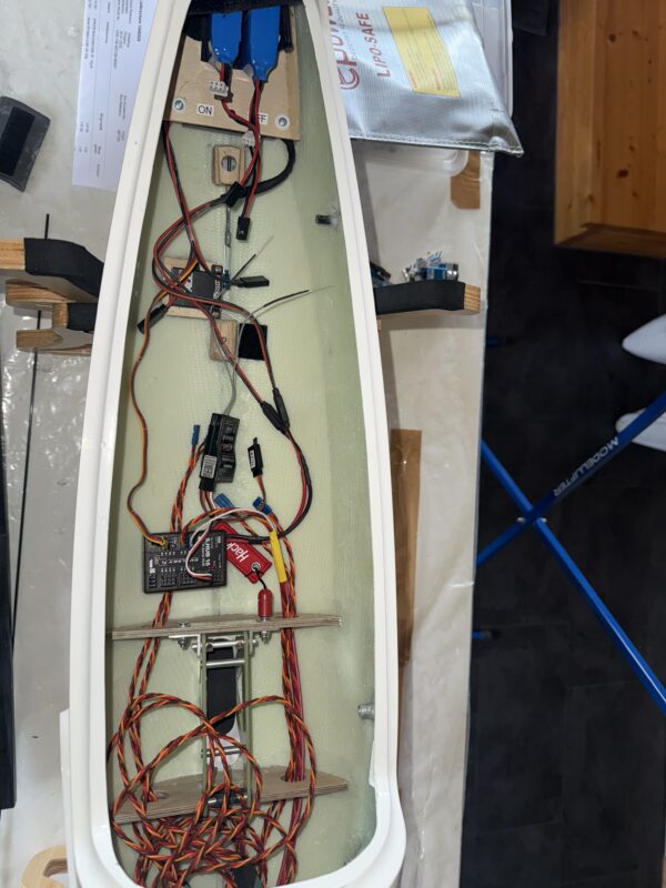
While waiting for the silicon to cure I finished work on the tailplane, wiring and fuselage. In the V-tail I installed two KST X08H Plus servos, which are light and relatively powerful. To avoid any play I splashed out on the expensive but really nice servo frame and LDS kit from Tomas Liu Studios. Rather than installing this as LDS I used a normal clevis and a carbon control horn in the control surface. It’s the first time I am using this set. Unfortunately the aluminium servo had a bit too much play on them, but I managed to reduce that to almost nothing using a drop of locktite. I’m pretty pleased with the final result, the installation is pretty tight, using the full throws of the servos, there is virtually no play and the setup looks good as well. The tips of the V-tail were painted dark red. I’ll do the same with the wings once these are done.
Power for the glider comes from 2x 2S LIPO batteries, reduced to 7.4v through a Hacker/Emcotec Dualbat DPSI (with magnetic switch). I’m using this system for all my gliders and am very happy with it. All the wiring has been prepared, I’m waiting until the wings are finalised to balance the glider and deterimine the final position of all the components.
I weighed the total setup, and I expect the glider to have a flying weight of around 3.6kg – including around 60gr of lead in the nose. Pretty good.
All that remains now is setting the seals for the control surfaces of the wings, installing the servos and then finalising the programming.
There are quite a few Monerais still out there, including some for sale, but not too many good quality pictures or designs that caught my liking.
To my surprise I found that there are several Monerais that were built and registered in Belgium. Two of these can be found on the website of the Aviation Society of Antwerp – the OO-70 (with pylon motor) and the OO-72. Coincidentally, I’ve traditionally given all my gliders without FES a Belgian registration number. So the decision was very easy to go for the OO-70 registration number for my Monerai. Unfortunaly the picture on the website of the Aviation Society of Antwerp isn’t too clear on the rest of the decals and since the Monerais were often repainted and changed I decided to go for my own design.
As information on the Monerai is starting to disappear from the web (the website containing the plans and building information is no longer online), I post a cleaned up version of the logo of the monerai here.
Cutting out the control surfaces always makes me nervous and I tend to push it off until I feel that I’m really up for it, with a clear mind and a steady hand. So much can go wrong and it can really mess up your build. Fortunately I’ve never messed it up so much that it wasn’t salvagable and the final plane looked crap.
We usually set the hinges of the wings at the bottom and the tailplane at the top of the wing. The reason for this is that the “seal” for the gap on the tailplane is tape (easier), whereas we do set a seal at the upper side of the control surfaces for the wings (more on that later). Most importantly, you want the airbrakes (inner control surfaces) hinged at the bottom to allow maximum throw.
To cut out the control surfaces we use a hand-held milling machine – basically an old Dremel with a brass add-on made ages ago by a club colleague (see picture). This brass add-on allows you to pull the dremel along a ruler or aluminium profile or bar. The aluminium profile is fixed to the wing with bits of double-sided tape. The starting and end-points are defined by the little holes in the surface of the wing that I made before bagging the underside of the wing and are positioned between the two rear spars of the wing (and the holes were kept open during the various stages of building the wings including the spray painting).
For the top of the wing I use a 2mm milling bit, for the underside (where the hinge comes) I use a 1mm milling bit (the reverse for the tailplane). I’ve learned the hard way that it’s worth investing in good quality milling bits that are made for cutting carbon fibers – the cheapo chinese bits don’t last very long. I’ve also built a foot-controlled switch so that I can turn on and switch off my Dremel with my foot and don’t have to use the switch on the Dremel itself. Make sure that you pull the Dremel along the profile from left to right, with the profile at the underside of the Dremel (if it rotates to the right it will pull the Dremel nicely against the aluminium profile and reduces the risk of it “wandering off” and messing up your wing).
After cutting the long horizontal bits I carefully separate the control surfaces using a small saw. Then I clean out the foam, lightly sand all the corners and surfaces that are cleared of foam. The wings then need much more work still, more on that later.
Cutting out the openings for the servos is done in a similar manner. We have small templates that we tape to the wing using double-sided tape and then cut out the openings using the dremel with a 1mm milling bit.
The next step on the tailplane is to check if any bits need protection or correction using a some resin (if necessary coloured white). After that I position the control surfaces using good quality wax tape and 1mm thick pieces of balsa-wood. I then apply silicon glue (Wacker Elastosil E41) using a syringe with a 3/2 mm aluminium tube, wiggle the control surface a couple of times and then fix in place using leftover bits of ebechi wood with double-sided tape. Leave that to cure for 3-4 days and then carefully remove the wax tape (don’t pull out the silicon!) and the tailplane is ready for the servos to be built in.
Over the weekend I’ve been doing some background research into the Neukom Elfe S3 – in particular to find more information for the decals and cockpit for our Elfe. This post summarises the main points that I’ve found, as an effort to bring together key bits of information for further use as we work on our models. Note that Neukom was known for continuously improving/tinkering with his gliders, there are various versions of the S3, the below list also includes the S2/3, bot the x-tail and v-tail versions.
As far as I could find, in total 12 ELFE S3 (including a few S2/3) were registered in Switzerland over the years. Only two of these seems to be registered/flying in Switzerland still. Two were exported to the US and are still registered there. One is in the Transport museum in Lucerne:
HB-902, ELFE S 3 P, Baujahr 1968 Werknummer 18: still registered, stationed in Schmerlat
HB-903, ELFE S 3 P, Baujahr 1968 Werknummer 17: removed from the aircraft registry on 16 August 2012 following serious damage after outlanding on 4 August 2012. Official incident report (p. 41-42)
I’m still looking for good pictures from the cockpit. Below are two screen grabs that I took from the 1968 TV documentary.
Addition 3/3/2025: our club colleague Willy W. obtained a further picture of the “old” cockpit of the HB-902. Apparently it’s been modernised now, and we hope to get a picture of the newer version as well. I’ll be adding pictures below as we receive them.
Addition 12/3/2025: our club colleague Willy W. now also obtained a further picture of the current cockpit of the HB-977. I’ve added the picture below.
Although the paintjob on my Monnett Monerai was really good, we like to polish our gliders after they are painted and the paint is fully set (usually takes a few weeks). Polishing the paint gives the glider that bit of extra gloss and smooth surfaces and gets rid of the slight “orange skin” structure in the paint. It’s a lot of work though. I divided it over three days, around 2-3 hours each day.
A short “how to”: First we get rid of the orange skin structure by wet sanding all painted surfaces with 800 grit sanding pads (Georg even starts with 600 grit sandpaper), followed by 1500 grit and then a 3000 grit sanding pad (all by hand). After that we machine polish all surfaces using a fast cut compound, followed by a machine polish compound. See the last picture below for the materials used. In Switzerland we purchase all materials through sury.ch – unfortunately only in larger quantities, but then they last a lifetime of building gliders.
We use a standard carbon wing joiner for most of our projects. It’s slightly conical and has a 6 degree V-shape/Dihedral. See the picture below for the sizes of the joiner resulting from the mould. The mould for the wing joiner is close to 20 years old. It’s a pretty simple setup, made of wood and aluminium. It has been used countless times and is still going strong. For the Elfe S3 we reduced the dihedral of the mould to 1 degree (the mould allows for this).
Here’s a description of how we build wing joiners out of this mould. All references to materials are to the R&G Webshop.
Setup:
The setup consists of 1) a roll of CF-Roving Tenax-E HTS40 F13 24K 1600tex (Art. 205.0024), mounted on an easy-rolling dispenser; 2) a 70ml syringe with a short piece of tube (I use motorcycle fuel lines) mounted in a self-made holder (to drench the roving with resin)(the syringe is held by a standard broom holder); 3) a small turntable to help cut the carbon roving to the right size; and 4) the mould. See the pictures below for more detail. The syringe and turntable are screwed to my workbench to make sure they stay in place.
Waxing the mould:
We apply three coats of liquid wax. Allow each coat to dry and then lightly polish with a piece of soft cloth. Apply some bicycle grease to the screws to close the mould (to avoid them getting stuck due to a bit of wayward resin).
Prepare the core of the joiner:
Previously we used a rohacell core for our wing joiners. For more recent builds we’ve found that it’s much easier (and cheaper) to use a balsa wood core. We use either 4mm or 6mm balsa. This is put into a 3K carbon sleeve (35mmØ 3K, Art. 200.4008).
Epoxy Resin:
I use two small joghurt cups to prepare the resin. Amounts needed:
I use black colourant to get nice and black wing joiners.
Set aside and thicken some of the resin in the 2nd cup (Aerosil) to apply to the mould and cover of the mould.
Building the joiner:
Apply epoxy resin to the balsa core (in the sleeve) using a small brush.
Apply thickened epoxy resin to the mould (this is to ensure that the surface of the wing joiner is nice and even, without air bubbles)
Then roll carbon rovings onto the turntable. I roll them in sets of 8. Use scissors to cut them into separate rovings at the right length.
Evenly put the rovings into the mould, starting at the edges.
Regularly spread out the rovings in the mould using an old credit card or a piece of wood .
The amount of rovings to use is as follows:
Wing Joiner with 4mm Balsa Core:
50 Rovings above and + 50 rovings below the core. In addition, add on each side of the core 4x13mm und 3x 17mm rovings in the center
Wing Joiner with 6mm Balsa Core:
40 Rovings above and + 40 rovings below the core. In addition, add on each side of the core 4x13mm und 3x 17mm rovings in the center
Note that you may need up to three rovings more on each side, depending on how much resin the rovings absorb (this can be adjusted by squeezing the tube coming out of the syringe – see picture)
Once all rovings and the core are in the mould, close the mould and let the resin cure for a few days.
Our plug builder Richi has been working hard over the holidays and made good progress on the plug for the Elfe S3. Earlier this week he dropped it off at our airfoil designer Georg so that he can prepare the connections for the elevator and the wings to the fuselage.
During the holidays Georg also modified our standard wing joiner mould, decreasing the dihedral to 1 degrees – which we will be building into the root of the wing in addition to the dihedral halfway through the wing. Today I used the mould to build the first wing joiner. See the separate “how to” post on how we build our wing joiners.
We’ve started a new project with our building team: the Neukom Elfe S3. The Elfe S3 is a 15m glider, designed in Switzerland by Albert Neukom. It was first flown in 1966 and entered production that same year.
We are not aware of any recent scale models of the Elfe S3 in this size and, as usual, we don’t have much in terms of original plans to work from. Thankfully the glider compendium of Martin Simons (1965-2000) contains a good A4 drawing. I’ve had this drawing enlarged to full scale, so that our building team member and plug builder Richi can start work on the plug for the fuselage. Georg has started designing the wings. We are likely to build the moulds for the fuselage in Autumn 2025 and the first models in the winter of 2025-26, in the hope that we can maiden our first Elfe S3 in spring 2026.
We will be building a 1:3.5 scale version, so a wingspan of 4.28m. The airfoil will be our trusted MH-32, at 9% (1.7% curvature). We’ve been using this airfoil for our past few builds. It provides an optimal mix of excellent thermalling, speed and agility. We will also use six wing control surfaces and no air brakes. The tailplane will not be all-moving but we will use an elevator. We will also use a retractable gear, like the original.
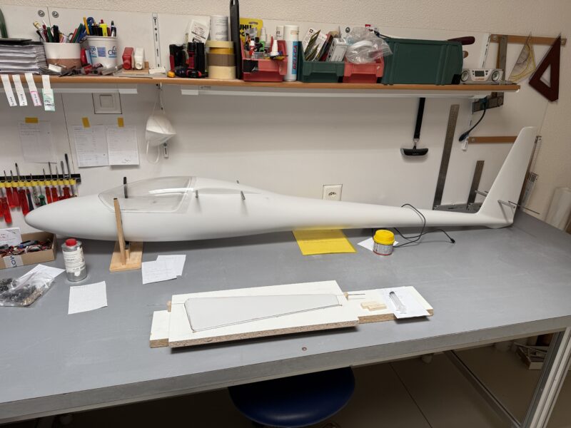
The Monnett Monerai has been back from the paint shop since early June 2024 already. It’s been sitting in my workshop waiting for the next step in the build. I hope to finally have some time to work on in the next few weeks and will post an update as soon as possible. Here’s a “teaser” from the assembled glider. Our building team member Andi did a great job once again spray painting it.
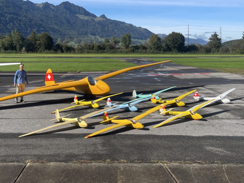
The original 1944 Moswey III HB-374 is owned by the Oldtimerclub Schänis, based at the Schänis Glider Airfield in Switzerland. It’s in excellent condition, airworthy and regularly flown.
Our club had the opportunity to bring together the original 1944 HB-374 Moswey III and our club’s Mosweys for a photo session. The photo session was an event that I was very much looking forward to attending. Unfortunately my attendance was thwarted last minute by a sudden COVID infection, requiring me to stay at home. Club colleagues and friends Georg, Andi, Paul and Willy thankfully made sure that all our club’s Mosweys, including mine, made it to the event and took some great pictures.
Clicking on the picture below brings you to the website of our club with all photos.
My trusty Futaba T18SZ is getting older and has had many hours of flight time – without any issues. As I don’t want to change to another system (Futaba never failed me, I have loads of receivers and I’m too lazy to re-program all my gliders on a new system) I was keen to try out the newly released Futaba T26SZ. As soon as one popped up in the inventory of one of my local model shops yesterday afternoon I rushed out and got it.
This afternoon I had my first flights with the new transmitter. Here are my first impressions.
First the good things:
One of the reasons that I always liked my T18SZ is the low weight. The T26SZ is 5 grammes lighter (922gr), very easy to handle and much lighter than some of the other brands.
The sticks feel great, very similar to what I was used to on the T18SZ. “Potless” sticks have been the rage over the last few years and are now standard on the T26SZ (although I’ve yet to meet anybody who had issues with the sticks on the standard T18SZ).
The operating system of the T26SZ is essentially that of the T18SZ, with a few extra “gimmicks”. That makes it easy to dive straight into. I was particularly pleased that the T26SZ did not build upon that of the T32MZ, which, in my view, is over-engineered and a pain to use. The model picture on the display as well as the possibility to assign sounds to switches are a nice new addition. Many will also appreciate the elaborate sequencing options.
A great plus is the 2nd screen at the top of the transmitter. It’s very easy to read and “always on”, providing the option to show either telemetry data or the timers (I’ve chosen the latter, as my telemetrics come via headphone). Another benefit is the new antenna, which is much less vulnerable and exposed than that on the T18SZ (I’ve seen them broken off on multiple occasions).
Transferring the first few models from my T18SZ to the T26SZ was a breeze, using a micro-SD card with a converter to a standard SD card. When copying the models from the card onto the T26SZ it automatically and instantly converts them to the new transmitter. All that remains is binding the receiver(s) as well as installing telemetry. Easy. I’ve not found any conversion errors so far.
There are a few things that I’m not so satisfied with. Some of them I hope will be addressed in future software updates or as I explore the transmitter’s possibilities:
My main issue is with the sliders at the lower right and left of the T26SZ. As a glider pilot I use the lower left slider for the motor and the lower right glider to switch between different positive camber positions (I usually have three). The new sliders are much smaller, do not have much resistance (move too easily) and do not feel very precise. Whereas that’s simply annoying with the camber positions, it can be dangerous with the motor. Even though I use a safety switch for the motor on the transmitter, it’s (too) easy to touch the slider and engage (or disengage) the motor. Probably much of this just takes getting used to. I do however want to check if there’s a way to give the sliders a bit more resistance. I’ve yet to make up my mind if I like the fact that there are now two sliders on each side rather than the single slider on the T18SZ. On the left side I will probably tape over the outer slider.
A real pain is that the number of models that can be stored on the transmitter itself remains limited to 30 and you cannot operate a model from the SD Card. I had hoped that this number would have been increased. I’m about to hit the 30 limit on my T18SZ and dislike having to copy models from/to the SD Card (yes, I fly all my models, I’ve sold the ones I don’t fly).
Much less important, but still annoying, is the positioning of the micro-SD card. Getting the card it in and out is finnicky. Especially in the beginning I had to move the card it back and forth very often to get the hang of transferring the models and the model pictures onto the T26SZ. Once all my models are converted it should however be fine.
The model pictures option is fun, but requires some work as all pictures need to be exactly 160×80 pixels, in a 24bit BMP file and with maximum 8 characters in the file name. Do one thing wrong and it’s not recognized by the system. No mercy.
Even though there is a whole range of pre-defined sounds, there are some that I would have liked that are missing (camber settings) and all of them are in English only. I’ve not found a possibility to add new or custom sounds.
Can I please rename my telemetry sensors? I mostly use my SM Modellbau GPS Logger 3 and find the “borrowing” of wrong sensor names simply annoying.
The two functions that I missed most when I transferred from my T14SG to my T18SZ have not been brought back: autolock of the screen/menus (after x seconds) and the ability to adjust the telemetry volume through one of the dials on top of the transmitter. While that’s not a disadvantage compared to the T18SZ, it is a missed opportunity for the T26SZ. I spend much of my time on the slope and would like to be able to turn up the volume in strong winds/gusts. The manual is also very explicit about the need to lock the touch-screen, so an autolock really would make sense.
One final point to raise is that I’ve not yet been able to get my SM Modellbau GPS Logger 3 to work on the new transmitter. For some reason it gives weird values for the GPS sensor (multiplied by 256 and a minimum speed of 64kmh). There’s probably an easy fix for this, but I’ve yet to find it. [EDIT 30.9.2024: the new software update v.1.2 for the T26SZ remedies this problem – with many thanks to Arwico and Futaba for correcting this bug so quickly]
All in all my first impression is moderately positive, but I really need to use it more to form a definite opinion. So far, I find the transmitter an interesting evolution compared to the T18SZ, certainly not a revolution, that provides a number of improvements over the T18SZ, but also misses a few obvious chances. I was certainly not looking for a revolution in the new T26SZ, and am happy that it builds so much on the T18SZ. I do hope that the list of issues that I’m not too happy with will be reduced as I get to know the transmitter better and as Futaba comes with the inevitable software updates in the next few months.
I picked up my first 2.8m Swift from Uwe Freitag (Fridayfly) in December 2019. I’ve not flown it very often – usually a few times each year in Hahnenmoos on Lavey – but have had great fun with it. It’s the ultimate slope racer – so fast, and so robust, excellent for heavy duty slope conditions.
As the waiting list for Fridayfly planes is very long I immediately booked a building slot for a new plane when I picked up the 2.8m Swift. In December last year (2023) I got the long-awaited email that my building slot was coming up in June 2024. The really cool thing about Fridayfly is that you can decide on what plane you would like to have built in the months before your building slot comes up – in addition of course to any customisation of the plane. After a friendly call with Uwe I decided to go for the new 3.06m Swift. When I ordered it he had just maidened the new glider and was very pleased with the performance. As for the colour I decided to go for yellow with nice black and white stripes on the underside of the wings. Uwe completely built the plane for me – including installing the motor and all servos. All that was left for me to do was install the ESC, receiver, backup power and battery – and of course program the transmitter. My new Swift is now ready to maiden – watch this space!
I’ve sold my 2.8m Swift to my boss, the President of the Swiss Aeromodelling Federation, who will undoubtedly have loads of fun with it. I’ve also booked a new building slot – the next available was for the end of 2030…..
We’ve now had a few opportunities to fly our Chocofly DG800. We’re still tinkering with the settings, but are close to the final result. It’s a fun plane. With the large wingspan and short fuselage it’s very manoeuvrable and the airfoil allows both for good thermalling and faster flying. Without pushing it too much I got to 235kmh – more should be possible. At the same time it likes a bit of camber and can be thermalled really nice and slow. Here’s a video that I made from our flying yesterday. The air was very gusty and choppy, so not the best conditions for flying, but the DG800 dealt with it very well. Also note that the mix of the rudder and ailerons isn’t optimal yet, the plane should be more stable when we get that right.


You must be logged in to post a comment.