
After letting the silicon for the hinges of the wing control surfaces cure for four days I carefully removed the wax tape – this is always challenging as the tape sometimes pulls out the silicon.
The next step was making the seals between the control surfaces and the main wing. I use a heat-resistant tape and epoxy with white colourant, slightly thickened with micro-balloons and aerosil (caution: this should be quite liquid so that it sets nicely)! Using some tape I put the control surfaces in a 90 degrees angle and the wings in a 90 degree angle to the worktop. With a syringe I applied the epoxy on the heat-resistant tape. I let this cure for a few hours – just so that it’s still flexible but no longer liquid. I then carefully put the control surfaces back to around 20-30 degrees downward angle from the main wing, using a ruler to make sure that the heat-resistant tape with epoxy slides under the surface of the wing. I then let the epoxy cure in this position. Once cured, I removed the tape and sanded the top of the new seal back – ensuring that I have enough thrown in all the control surfaces.
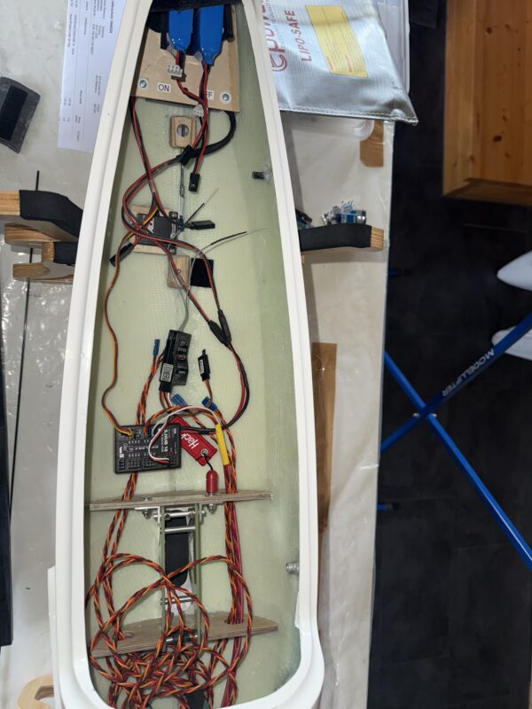
Next up was installing the wing servos. I use the Chocofly LDS Pro system, with Chocomotion Servos. The LDS system is relatively easy to install thanks to the 3mm pushrod that can be extended or shortened to the perfect length. Most importantly, the LDS system is entirely free of play. I always first glue in the wing control horns using 5min epoxy and then the servo frames, also using 5min epoxy. I then fix both using my regular epoxy. I apply a bit of liquid CA to ensure that the push rods are free of any play and a bit of 5mm epoxy to ensure that the small pin on the servo control horn remains in place.


You must be logged in to post a comment.